
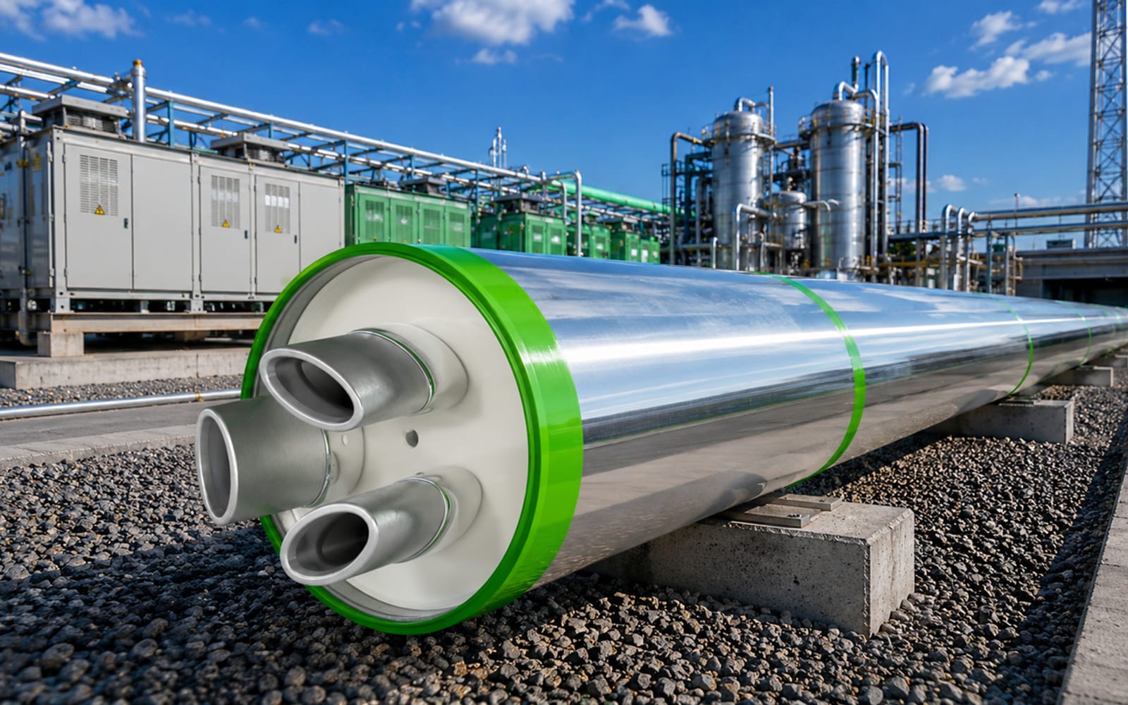
Pressurized Air Cables (PAC)
High-pressurized
air cable systems
Heavy-duty power transmission insulated with clean compressed technical air — SF6-free, PFAS-free, low-loss and continuously monitored. Basmni engineers, supplies and commissions PAC systems for high-voltage substations, dense grid corridors and hydropower evacuation.
Overview
Power transmission insulated with pressurized air
Pressurized Air Cable (PAC) systems move large blocks of power through a sealed metallic pipe insulated with clean, dry technical air instead of SF6 gas or fluorinated polymers. The result is a heavy-duty transmission link with the capacity of a gas-insulated line and none of its greenhouse-gas exposure.
Basmni engineers, supplies and commissions PAC systems for high-voltage substations, dense grid corridors and hydropower evacuation — where large conductor cross-sections, low losses and a compact right-of-way matter more than anything else.
How PAC works
Three functions, one sealed pipe
Transmit power
Large aluminium conductors — frequently exceeding 2,200 mm² — carry high continuous current with low ohmic resistance, so the system runs cooler and wastes less energy than a comparable polymeric cable.
Insulate with pressurized air
Clean dry technical air, or a controlled nitrogen–oxygen mixture, is held under pressure inside the enclosure as the dielectric. There is no SF6, no PFAS and no insulating fluid, so the global-warming-potential factor of the insulation is zero.
Monitor continuously
Integrated sensors track internal pressure, gas density and temperature in real time. Operators see the condition of the link continuously and can plan maintenance around measured data rather than fixed intervals.
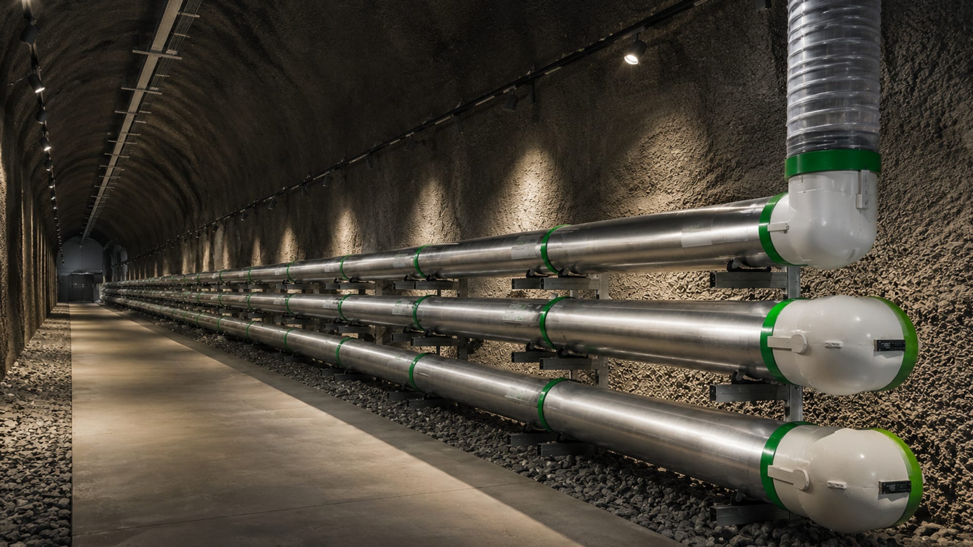
Key features
What makes PAC different
Capacity, efficiency, a clean insulating medium and built-in monitoring in one metallic system.
High transmission capacity
Rated for continuous current up to 5,000 A at voltages up to 420 kV without excessive thermal degradation.
Lower transmission losses
Large aluminium cross-sections cut resistive heating; losses run 2× to 10× below standard underground polymeric cables.
PFAS- and SF6-free insulation
Clean dry technical air or nitrogen–oxygen mixtures replace fluorinated polymers and SF6 entirely — zero insulation global-warming potential.
Integrated condition monitoring
Continuous real-time telemetry of internal pressure, gas density and localised temperature is built into the system, not bolted on.
Compact system architecture
Modular piping is routed through microtunnels, service corridors and narrow utility bridges — no external forced-cooling plant.
Reduced external electromagnetic fields
The rigid metallic enclosure behaves as a Faraday cage, holding external magnetic fields to minimal levels along the route.
Flexible, modular installation
Standardised pipe modules adapt to varied routes — new ducts, reused tunnels, bridges and confined substation approaches.
Robust metallic enclosure
Hermetically sealed, pressure-monitored compartments give a projected operational life beyond 40 years with minimal maintenance.
Why pressurized air
SF6-free. PFAS-free. Just clean air
Conventional gas-insulated transmission relies on SF6 — a gas with a very high global-warming potential — while polymeric cable systems depend on fluorinated chemistry. PAC uses clean dry technical air, or a controlled nitrogen–oxygen mixture, held under pressure as the dielectric.
The insulation contributes zero global-warming potential, there is no fluoropolymer to manage over the life of the asset, and the electrical strength needed for high-voltage operation is retained.
Key components
What a PAC system is made of
Technical specifications
Basmni PAC system parameters
| Voltage rating | Up to 420 kV |
|---|---|
| Continuous current | Up to 5,000 A |
| Transmission losses | 2×–10× below polymeric cable |
| Conductor | Aluminium, > 2,200 mm² |
| Cooling | Passive — no forced cooling |
| Projected life | > 40 years |
Technology reference
Voltage and current figures above are Basmni system parameters drawn from Basmni technical material. Wider industry references for pressurized-air / gas-insulated transmission sometimes quote different envelopes (for example higher bulk-transfer ratings or a lower voltage bound); those are technology-reference figures, not Basmni specifications, and any project is engineered to its own rated parameters.
Solutions by grid level
Where PAC fits across the grid
From transmission networks and substations to specialised high-current applications — engineered to the rated parameters of each project.
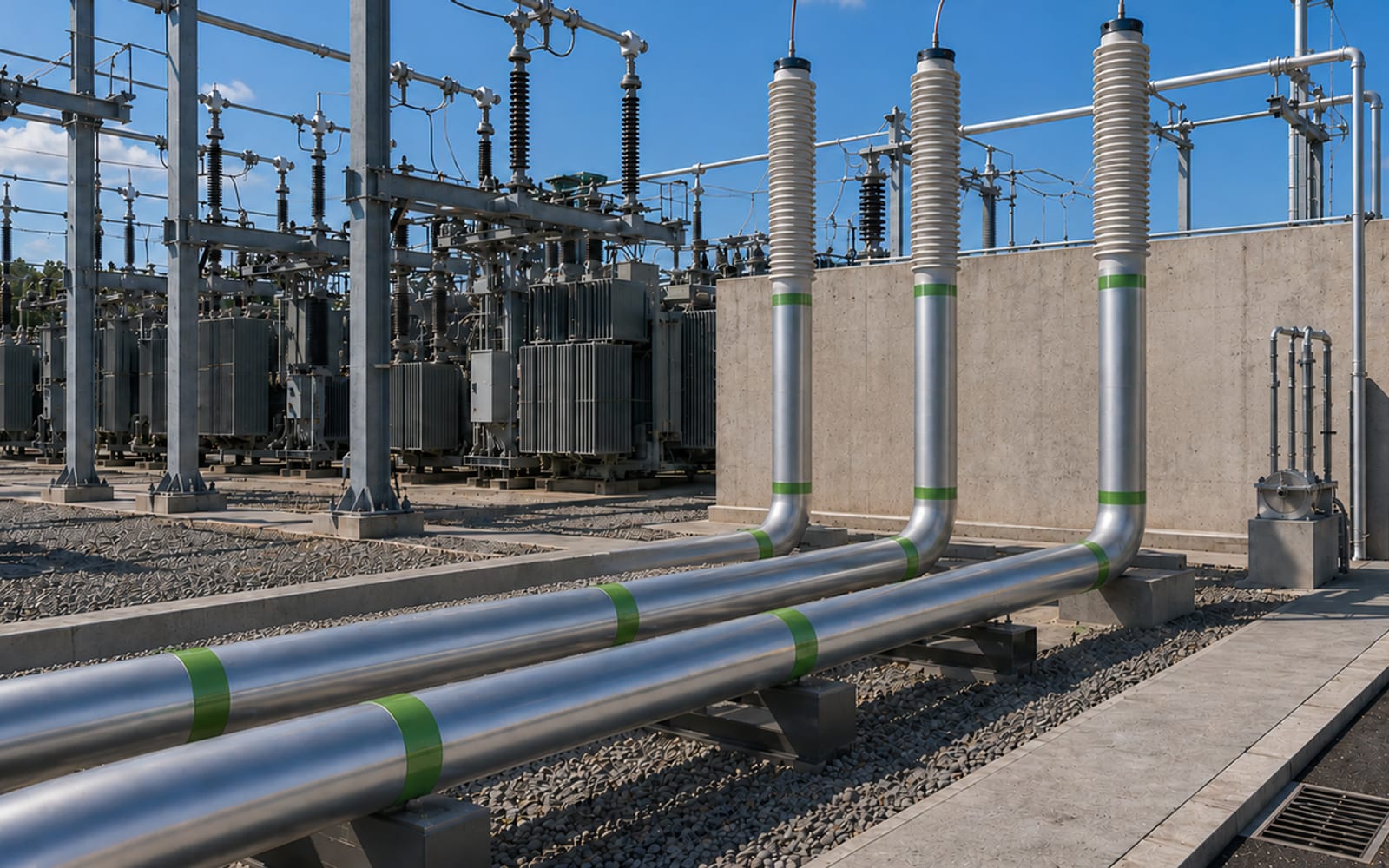
High-voltage networks
High-performance links for transmission networks and grid-expansion projects — moving large blocks of power over medium and long distances with low losses and a narrow right-of-way.
Medium-voltage networks
Compact, efficient feeds for industrial facilities, critical infrastructure and regional distribution networks with demanding power requirements.
Substations & switchgear
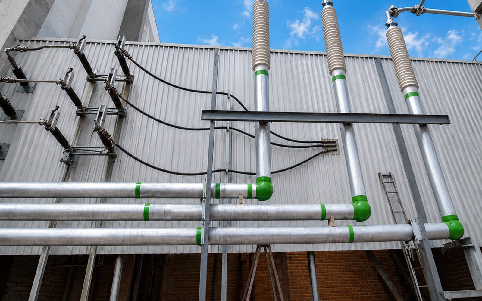
One phase per pressurized-air duct — a flexible architecture for connections into and between high-voltage substations up to 420 kV, including gas-insulated switchgear connections and wall bushings.
Specialised & high-current applications
Engineered for battery energy storage systems, data centres, hydrogen facilities and other loads that need high current capacity within a limited footprint.
Comparison
PAC vs established alternatives
How a pressurized-air cable compares with underground XLPE cable and with overhead lines.
PAC vs XLPE cable
Transmission capacity
Pressurized Air Cable
High — large aluminium cross-sections, up to 5,000 A at up to 420 kV.
Conventional XLPE cable
Limited by conductor size and thermal rating for a given trench.
Transmission losses
Pressurized Air Cable
2×–10× lower than standard underground polymeric cable.
Conventional XLPE cable
Higher resistive losses for equivalent current.
Condition monitoring
Pressurized Air Cable
Integrated — continuous pressure, gas-density and temperature telemetry.
Conventional XLPE cable
Typically added separately, if at all.
Insulating medium
Pressurized Air Cable
Clean dry technical air / nitrogen–oxygen — SF6-free and PFAS-free.
Conventional XLPE cable
Cross-linked polymer insulation (XLPE); SF6 in gas-insulated variants.
Cooling
Pressurized Air Cable
Passive — large-profile enclosure dissipates heat, no forced-cooling plant.
Conventional XLPE cable
May require forced cooling at high load.
External magnetic field
Pressurized Air Cable
Low — rigid metallic enclosure acts as a Faraday cage.
Conventional XLPE cable
Field management depends on laying arrangement and screening.
Installation flexibility
Pressurized Air Cable
Modular piping through new ducts, reused tunnels, bridges and corridors.
Conventional XLPE cable
Continuous trenching or dedicated cable tunnel.
| Criteria | Pressurized Air Cable | Conventional XLPE cable |
|---|---|---|
| Transmission capacity | High — large aluminium cross-sections, up to 5,000 A at up to 420 kV. | Limited by conductor size and thermal rating for a given trench. |
| Transmission losses | 2×–10× lower than standard underground polymeric cable. | Higher resistive losses for equivalent current. |
| Condition monitoring | Integrated — continuous pressure, gas-density and temperature telemetry. | Typically added separately, if at all. |
| Insulating medium | Clean dry technical air / nitrogen–oxygen — SF6-free and PFAS-free. | Cross-linked polymer insulation (XLPE); SF6 in gas-insulated variants. |
| Cooling | Passive — large-profile enclosure dissipates heat, no forced-cooling plant. | May require forced cooling at high load. |
| External magnetic field | Low — rigid metallic enclosure acts as a Faraday cage. | Field management depends on laying arrangement and screening. |
| Installation flexibility | Modular piping through new ducts, reused tunnels, bridges and corridors. | Continuous trenching or dedicated cable tunnel. |
PAC vs overhead lines
Land use
Pressurized Air Cable
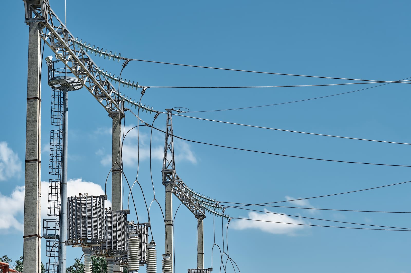
Underground route — a narrow permanent corridor with no visible structures.
Overhead lines (OHL)
A wide right-of-way with visible towers and conductors along the whole route.
Cost & materials
Pressurized Air Cable
Higher civil and material content for the enclosure and buried route.
Overhead lines (OHL)
Low material requirement and cost per kilometre on open ground.
Transmission performance
Pressurized Air Cable
High capacity and low losses in a compact, weather-independent cross-section.
Overhead lines (OHL)
Proven high capacity, but rating varies with weather and conductor spacing.
Environmental & visual impact
Pressurized Air Cable
No overhead structures; low external magnetic field from the metallic enclosure.
Overhead lines (OHL)
Visual intrusion and a larger electromagnetic footprint at ground level.
Grid-expansion acceptance
Pressurized Air Cable
Easier to route through built-up and sensitive areas where overhead lines are opposed.
Overhead lines (OHL)
Faster to build on open land, but planning can be slow near settlements.
| Criteria | Pressurized Air Cable | Overhead lines (OHL) |
|---|---|---|
| Land use | Underground route — a narrow permanent corridor with no visible structures. | A wide right-of-way with visible towers and conductors along the whole route. |
| Cost & materials | Higher civil and material content for the enclosure and buried route. | Low material requirement and cost per kilometre on open ground. |
| Transmission performance | High capacity and low losses in a compact, weather-independent cross-section. | Proven high capacity, but rating varies with weather and conductor spacing. |
| Environmental & visual impact | No overhead structures; low external magnetic field from the metallic enclosure. | Visual intrusion and a larger electromagnetic footprint at ground level. |
| Grid-expansion acceptance | Easier to route through built-up and sensitive areas where overhead lines are opposed. | Faster to build on open land, but planning can be slow near settlements. |
Proven engineering
Established principles, a cleaner architecture
- ✓Voltage levels up to 420 kV
- ✓PFAS- and SF6-free insulation
- ✓Built on established gas-insulated transmission engineering
- ✓Continuous condition monitoring for safe, reliable operation
- ✓Suited to transmission, distribution and industrial applications
PAC combines the proven engineering principles of gas-insulated transmission with a pressurized-air architecture, giving a sustainable, high-performance route for modern medium- and high-voltage networks.
Technology reference
Wider references for pressurized-air / gas-insulated transmission cite their own validation testing and pilot installations. Those belong to the technology as a class; every Basmni link is engineered and tested to its own rated parameters.
Pressure & condition monitoring
The system tells you how it is doing
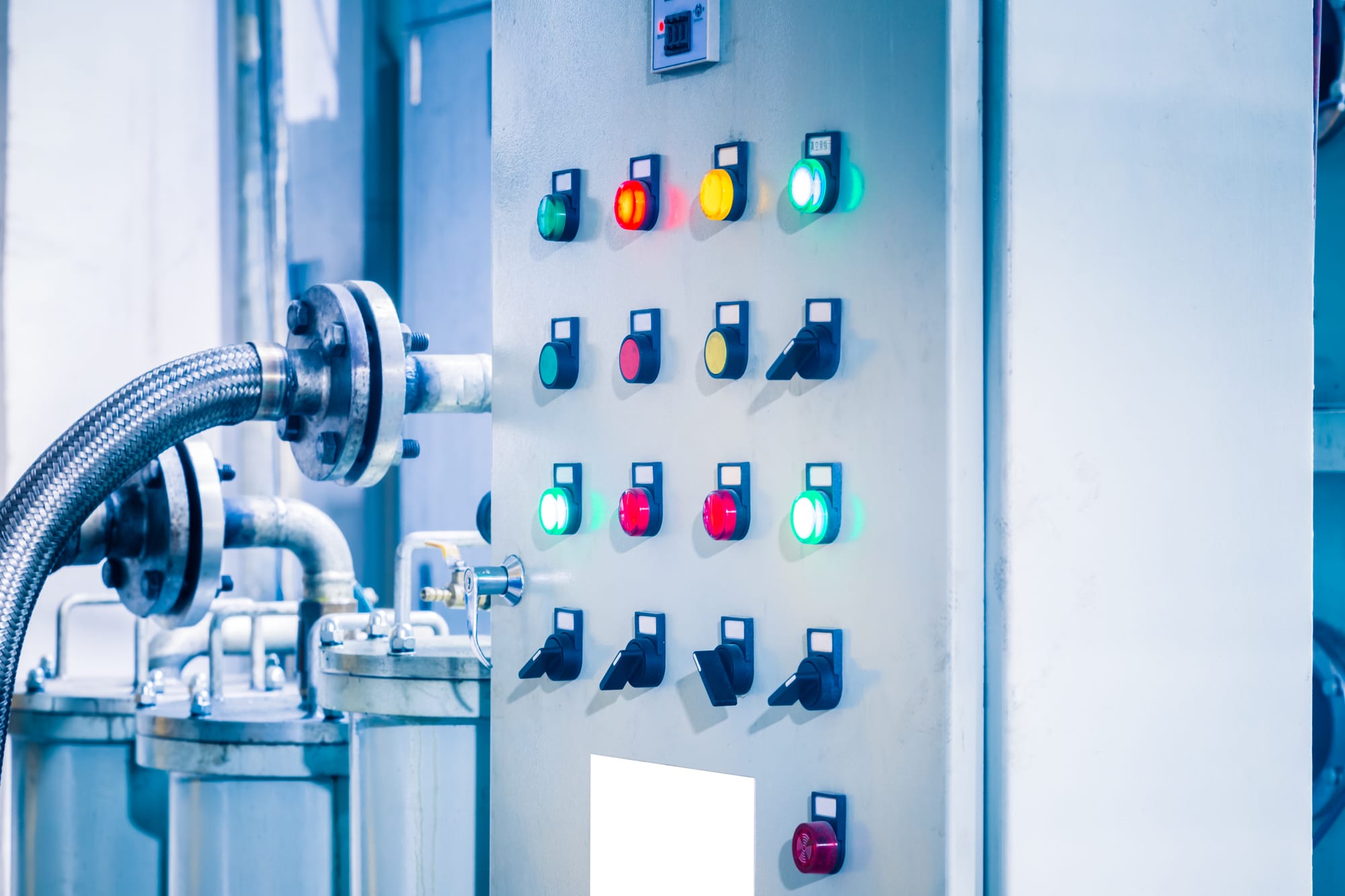
Monitoring is part of the design, not an add-on. Continuous measurement gives the operator a transparent, real-time picture of link health and turns maintenance into a planned activity.
- Continuous measurement of internal pressure across the sealed compartments.
- Real-time monitoring of gas density and localised conductor temperature.
- Early detection of a change in operating condition before it affects service.
- Maintenance planned around measured data rather than fixed time intervals.
- A continuous, transparent picture of link health for the operator.
Engineering & installation
One accountable scope
Basmni takes a PAC link from first study to energised system as one accountable scope — route engineering, system design, pipe installation and commissioning tests.
Engineering
Design
Installation
Commissioning
Engineering support
Work with our engineering team
Whether you are a grid operator, an industrial company or an infrastructure developer, Basmni supports you in evaluating and integrating a PAC system.
Technical feasibility assessments
A route, voltage, current and site review to confirm PAC is the right fit before design begins.
Application & project consulting
Configuration advice for transmission, distribution and industrial use cases.
Technical documentation & test reports
The drawings, calculations and commissioning records needed to approve and operate the link.
Direct access to the engineering team
A direct line to the engineers who design and commission the system.
FAQ